

Thermal Synchrotron Disk
This example ray traces an optically thick accretion disk of thermal electrons, and shows how the image changes as the disk goes from optically thick to optically thin with increasing observing frequency.
Unlike the power law materials, Krang.ThermalSynchrotron absorbs its own emission: it reports the source function and an optical depth for each sub-image, and render solves the transfer along the ray. That is what produces the limb brightened ring below.
using Krang
import CairoMakie as CMk

curr_theme = CMk.Theme(
    Axis = (
        xticksvisible = false,
        xticklabelsvisible = false,
        yticksvisible = false,
        yticklabelsvisible = false,
        aspect = 1,
    ),
)
CMk.set_theme!(CMk.merge!(curr_theme, CMk.theme_latexfonts()))
The model
We will use parameters loosely based on M87*: a
G = 6.6743e-11                      # m³ kg⁻¹ s⁻²
Msun = 1.988409870698051e30         # kg
rg = G * 6.5e9 * Msun / Krang.C_SI^2  # gravitational radius in metres

metric = Krang.Kerr(15 / 16);
θo = 17 * π / 180;
ρmax = 12.0;
The electron density, temperature and magnetic field each fall off as a power law in radius about a reference radius rb, and the fluid orbits with a speed of
rb = 5.0                  # reference radius, in GM/c²
n_th0 = 3.0e9             # electron density at rb, m⁻³
t_e0 = 3.0e10             # electron temperature at rb, K
magnetic_field = (0.0, 8.0, 0.0)   # at rb, in Gauss
fluid_velocity = (0.5, π / 2, π / 2)
p_dens, p_temp, p_b = -0.7, -1.5, -1.5;
The disk is the
function disk(ν)
    material = Krang.ThermalSynchrotron(
        magnetic_field...,
        fluid_velocity...,
        p_dens,
        p_temp,
        p_b,
        n_th0,
        t_e0,
        rb,
        ν,
        rg,
        (0, 1),
    )
    return Krang.Mesh(Krang.ConeGeometry(π / 2), material)
end

camera = Krang.IntensityCamera(metric, θo, -ρmax, ρmax, -ρmax, ρmax, 400);
Intensity and optical depth
render hands back the intensity, but raytrace on a single mesh returns the Krang.AbsorptiveIntensity it was accumulated from, so the optical depth the ray picked up is available alongside it.
slabs = Krang.raytrace(camera, disk(230.0e9));
intensity = map(x -> x.I, slabs);
optical_depth = map(x -> x.τ, slabs);

fig = CMk.Figure(size = (850, 400));
ax1 = CMk.Axis(fig[1, 1], title = "Intensity at 230 GHz")
ax2 = CMk.Axis(fig[1, 3], title = "Optical depth at 230 GHz")
hm1 = CMk.heatmap!(ax1, intensity, colormap = :afmhot)
hm2 = CMk.heatmap!(
    ax2,
    log10.(max.(optical_depth, 1e-12)),
    colormap = :viridis,
    colorrange = (-6, 1),
)
CMk.Colorbar(fig[1, 2], hm1, label = "W m⁻² Hz⁻¹ sr⁻¹")
CMk.Colorbar(fig[1, 4], hm2, label = "log₁₀ τ")
CMk.save("thermal-disk-230.png", fig)
fig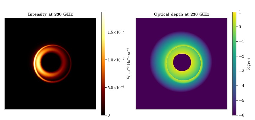
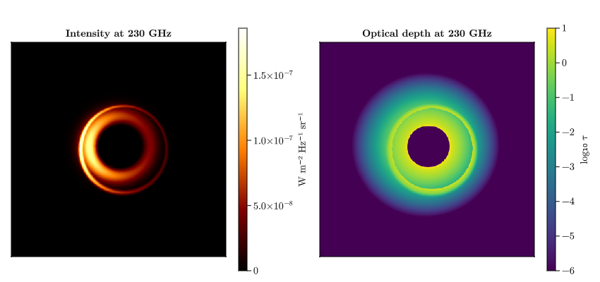
The bright ring sits where the disk becomes optically thick: only about 5% of the pixels reach
The left-right asymmetry is not an optical depth effect: the optical depth map is very nearly axisymmetric. It is Doppler beaming from the fluid, which orbits at
Walking through the transition
The critical frequency
frequencies = (86.0e9, 230.0e9, 345.0e9, 690.0e9)
fig = CMk.Figure(size = (1000, 280));
for (i, ν) in enumerate(frequencies)
    img = render(camera, Krang.Scene((disk(ν),)))
    ax = CMk.Axis(fig[1, i], title = "$(Int(ν / 1e9)) GHz")
    CMk.heatmap!(ax, img ./ maximum(img), colormap = :afmhot, colorrange = (0, 1))
end
CMk.save("thermal-disk-frequencies.png", fig)
fig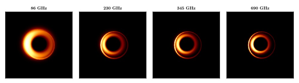
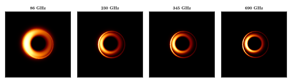
The low frequency image is a broad, saturated disk: it is optically thick out to large radii, so most rays simply return the local source function. As the frequency rises the emission narrows onto the inner disk – the horizontal cut through the centre tightens from
This page was generated using Literate.jl.